

How does it work
This power plant 100 kW can be divided into two parts:
1. Drive part (mechanical)
2. Electrical part (generator with automation and control)
1. The drive part consists of:
1.1. A metal tower filled with water
1.2. Metal baskets
1.3. Systems of chains, sprockets and gears through which speed reduction is performed
1.4. Compressors with supply pipes
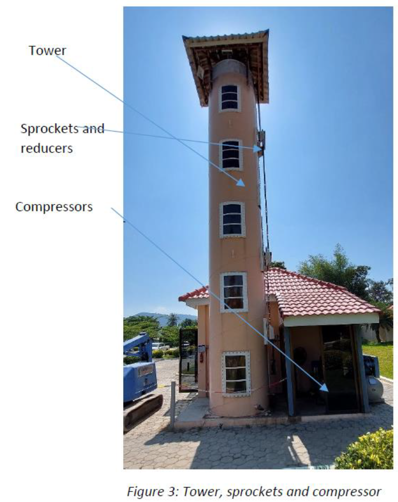
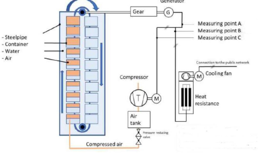
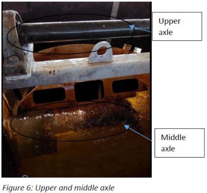
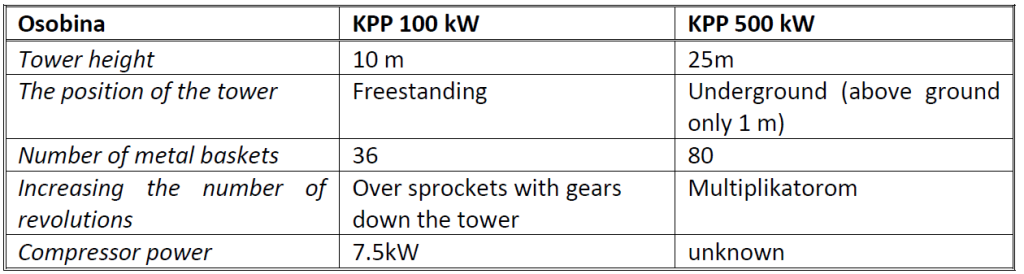
The metal tower at this power station is 10 m high and is filled with water. By construction, it consists of a metal pipe with a diameter of about 1.8 m, the thickness of the pipe wall is 5-10 mm. By construction, it is self-supporting without supporting beams, the method of foundation is unknown. There are 3 horizontal shafts inside the tower. Sprockets with two rows of chains are installed on the lower and middle shafts, through which the transmission is carried out. Baskets are fixed on the chains at the same intervals. The transmission from the middle to the uppermost shaft is also done by a chain. The purpose of the upper shaft is to “bring” the transmission inside the tower to a further system of chains, gears and reducers.There are a total of 36 metal baskets with a special design and made of special metal alloys. The compressor is connected to the tower via a high-pressure rubber hose. The compressor itself consists of a typical drive three-phase motor, a standard compressor, and a specially designed compressed air bottle.
The design of the bottle itself is a trade secret of the patent owner and the details are not shared. Two compressors are installed: primary and reserve. The primary is powered by the generator while the backup is powered by the grid. The owners of the facility claim that the spare is not included. What could be concluded from the tour was that he had not worked for a long time. The power of the compressor motor is 7 kW.
When the drive “comes out” of the tower via the third shaft, it is transmitted further by chains and sprockets. The speed is increased through gears placed at 4 points down the tower to a final speed of 375 revolutions per minute, which is finally handed over to the generator.
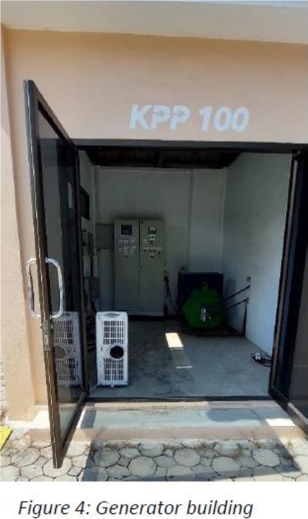
The generator therefore drives the chain at a speed of 375 revolutions/min. The energy produced by the generator is connected to the control cabinet. It was not possible to take pictures of the cabinets or open them, but it can be confirmed that the parameters on the instruments at the time of the visit were the same as those shown in the TUV and Dekra reports. The output voltage of the generator is 0.4 kV. The power of the generator is 100 kW. The generator is asynchronous and is synchronized with the compressor, which in the end gives a stable output judging by the parameters on the instruments and the reports.
The generator and the control cabinet are located in the generator building with an area of about 5m2. The compressors are covered at the back of the generator building. The tower is located next to and is covered by a canopy installed on the tower itself.
Whether it is a KKP 100 kW or KPP 500 kW, the way of functioning is the same.
The tower must be filled with water. Baskets are located on two rows of chains, the same number of baskets in two directions. The baskets are sunken, attached to two rows of chains and turn over the lower and middle shafts. For the purposes of this report, we will assume that the lower shaft is located at an elevation of 0 m and the middle shaft at an elevation of 10 m. In the zone of elevation 0, the water pressure is 1 bar. At elevation 0, compressed air is pumped into the basket in the upward direction. The air is pumped in at a precisely defined moment in a precisely defined amount through specially designed valves and thanks to a specially designed bottle on the compressor. The pumped air pushes the basket upwards, while the other side of the basket, which is filled with water, pulls the chains down. The next basket comes, which is filled with air, the upward thrust is stronger
and so on until all the baskets on the upward side are filled with air. Then the tower reaches full power and the system works circularly. The basket that reaches the top of the tower at an elevation of 10 m emerges from the water on free air pressure, turns, releases compressed air. The basket makes a circle through the open part of the tower and plunges into the water, fills with water and exerts downward pressure with its weight. From level 10 to level 11, the transfer is made from the middle axis to the upper one. The upper shaft drives the sprocket and the chain which further transmits revolutions to the gears which raise the speed several times (unknown exactly how many times) to the final speed for the generator.
KPP 100kW has been in operation for 3 years and, according to the owner, it almost did not stop production during those three years, except for the needs of tests, of which there were more.
The output voltage of both types of power plants is 0.4 KV. It is possible to raise the voltage of several production units to 10kV, 33kV or 35KV via a transformer and to further raise it to 110KV, 220KV, 400KV, depending on the total installed power and network conditions.